|
2.5 ISO
Photographers have long been able
to control the brightness of an exposure (i.e., a photo) by carefully
choosing an appropriate shutter speed
and aperture to accommodate
the luminance level (i.e.,
amount of light) available in a scene. (Shutter speed, aperture, and luminance are discussed in much
greater detail in Chapter 6). Since light levels in the field can
change drastically with different locations, different angles, and
different times (even as the sun goes in and out behind a cloud), a
photographer needs to be able to juggle these two parameters (shutter
speed and aperture) so as to avoid overexposure or underexposure in the
different field scenarios. Of course, doing this effectively
requires some skill, and in Chapter 6 we’ll cover the background
material needed for developing that skill.
With the advent of digital imaging, photographers
now have a third parameter at
their disposal for adjusting exposure: the ISO setting. Although
film photographers have long been able to adjust ISO by changing film
types (e.g., taking the ISO 100 film out of the camera and replacing it
with a roll of ISO 400 film, for example), in today’s DSLR’s you can
now change ISO from one photo to the next by simply turning a dial on
your camera before taking the next shot. Our purpose in this
section is to explain how ISO works in modern digital cameras and to
illustrate the importance of this feature for producing high-quality
images of birds, so that you can make a better informed decision next
time you buy a camera. Techniques for adjusting exposure in the
field via ISO settings, shutter speeds, and apertures are deferred to
Chapter 6, though the information covered here should serve as a useful
foundation for understanding the reasoning behind those techniques when
we cover them.
2.5.1 What is
ISO?
Just as with the acronym SLR, knowing what the letters in ISO stand for is unimportant.
What’s important to understand is that the ISO setting mimics the
effect of different film sensitivities. Thus, low ISO settings
mimic a low-sensitivity grade film, so that a longer exposure is needed
to collect enough light to get a bright image. Conversely, a high
ISO setting mimics a high-sensitivity grade film, in which more light
would be accumulated per unit time, allowing you to capture a bright
image with a faster shutter speed or smaller aperture. In this
way, you can think of the ISO dial on your camera as being a “brightness dial”—if all other settings of your
camera are kept constant, increasing the ISO will increase the
brightness of the resulting image. Unfortunately, it can also
increase the amount of noise
in your image.
Exactly how much the noise level will be affected by
an increase in ISO depends on a number of factors, but the magnitude of
this effect differs markedly between camera models. Whereas
consumer-grade DSLR cameras can, as of today, produce relatively
noise-free images at ISO 400 or less, and can often produce acceptably
noisy images at ISO’s as high as 800 or maybe 1000, pro-level DLSR’s
today can produce images with remarkably little noise at ISO 800 and
images with very tolerable amounts of noise at ISO 1600, or even 3200
for the full-frame models with large pixels. Indeed, whereas the
manufacturers appear to be battling each other for larger Megapixel
ratings in the consumer segment, they are to some degree battling over
better high ISO noise characteristics in the semi-pro and pro
markets. It’s useful to consider the types of “tricks” available
to manufacturers for improving the ability of their cameras to produce
low-noise images at higher ISO’s.
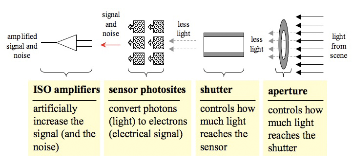
Fig. 2.5.1: How
ISO setting affects exposure.
Only the aperture and shutter (at right) affect the amount of light
reaching the sensor. After photons are converted to electrons by
the silicon matrix of the photosites, the ISO amplifiers artificially
increase the signal, but they also increase any noise that is present.
The first trick to be aware of is the noise-reduction-via-software
trick. Some manufacturers have been accused of trying to hide the
low quality of their CMOS sensors by applying a noise reduction filter
in the camera, after the image has been captured by the sensor and
before it has been written to the memory card. The problem with
doing this is that an aggressive noise reduction filter can end up
reducing the detail at the same time that it reduces the noise.
Thus, you may end up with images having very little noise, but also
very little detail (or sharpness). This does a great disservice
to the users of that company’s cameras, since it would be much better
to allow those users to manually apply noise reduction themselves after
downloading the image to their computer, where they can choose the
amount of noise reduction to apply, so as to retain the level of detail
needed.
A more “honest” approach is for manufacturers to
try
to improve the sensor’s innate ability to produce low-noise images even
when operated at higher ISO settings, without the need for subsequent
noise-reduction filters, and this is precisely what the big
manufacturers are trying to do. Before we can survey their
current efforts on this front, however, we need to dispel one very
popular myth regarding ISO: namely, that higher ISO settings on a
digital camera increase the sensor’s sensitivity to light and therefore
the amount of light captured, per unit time, by the sensor. This
is a very good analogy to what happens when a film photographer changes
to a higher-ISO film in order to collect more light in dim
scenes. Unfortunately, the analogy is wrong.
In digital cameras, light is collected by photodiodes made of silicon—the same material used to make
integrated circuits for computers. Photons of light striking the
(intentionally slightly impure) silicon lattice cause electrons to be
jarred free and to flow to metal leads where they are then channeled to
and stored in capacitors for eventual release to the further imaging
circuitry in the camera. The quantity of electrons collected from
a photodiode in this way correlates very closely with the number of
photons striking the pixel. Since different pixels are
constrained so as to receive only red, green, or blue photons of
different intensities, the electron counts of different pixels can
later be interpolated so as to infer composite color hues for
individual pixel elements in the resulting image. Thus, for
example, an overabundance of light waves in the blue part of the
spectrum striking a photosite will cause the blue component for that
pixel’s hue measurement to be dominant, and the resulting pixel in your
image should reflect this by showing a similar hue.
The key here is that all of this happens
irrespective of the ISO setting that you’ve dialed into the camera—at least, the parts of the story
involving electrons flowing in direct proportion to the number of
photons striking the photosite. The sensitivity of silicon atoms
to photons is in no way affected by the position of your ISO dial; it’s
determined entirely by the physical properties of silicon, and by the
concentration of impurities within the silicon lattice (called the doping ratio). Where the ISO
dial does have an effect is when the signal is later sent through an
analog amplifier
circuit, as shown in Fig. 2.5.1. The ISO setting is, in fact,
used to determine the
amount of amplification applied to the signal—also know as the gain. The problem is that the
amplification step amplifies both the signal and the noise, so that higher ISO
settings will necessarily result in images that are both brighter and
have a larger (absolute) amount of noise.
In order for manufacturers to reduce the amount of
noise inherent in high-ISO images produced by their sensors, they
therefore need to produce sensors having lower noise even at low ISO settings, since increasing
the ISO simply amplifies both the signal and the noise. This is
somewhat of an oversimplification, because what really matters is the signal-to-noise ratio (often
written as simply S/N), but
for our purposes, it will suffice to consider that the battle for
manufacturers is against noise, period, not against some phantom noise
source known as “high ISO noise”. In order to examine how
manufacturers are battling noise, we need to first consider the sources
of noise, which we do next.
2.5.2 Types
and Sources of Noise
First, let’s recall what noise
is. It’s the pixels in your image that are the wrong color, or
the wrong intensity (brightness). How does that happen?
There are many possible sources of noise, but two seem to dominate. The
first we’ve already mentioned in a previous section: sampling error. When the
pixels are small, and/or the exposure time is very, very short, the
actual count of photons striking each photosite may be very
small.
Since each photosite in a typical Bayer-type
sensor arrangement only registers one of the primary colors (red,
green, or blue), the actual pixel colors have to be reconstructed by interpolation (basically,
averaging) between the red, green, and blue measurements of the
physical photosites corresponding to that pixel. With small
sample sizes (i.e., when the actual number of photons collected is
small), that interpolation step can suffer from measurement error, and
the actual color that is computed for that pixel may differ to some
degree from the “correct” color for that pixel. The
amount of
error in the measurement can vary, and for some pixels there will
naturally be more error than in others, due to statistical
variation. The ones with the most error stand out most
prominently, and if there are lots of those erroneous pixels, then the
image appears noisy. This type of noise is called photon noise. When
photographing in low light with a camera having a very high pixel
density (i.e., very small pixels), photon noise can be a serious
problem.
The other main type of noise is called read noise, and is due to
electromagnetic interference (and, to a lesser degree, heat) from the
electrical circuitry associated with each photosite, such as the ISO amplifier (mentioned above) and
the analog-to-digital converter
(ADC), which converts electron counts into digital information (i.e.,
bits and bytes). Whereas the pixel density (or, more precisely,
photosite size) can be a fairly good predictor of a sensor’s tendency
toward sampling error, there is no simple way to guess the amount of
read noise that will be produced by a sensor’s electronics, based
solely on the manufacturer’s spec. The amount of read noise
produced by a sensor can be affected by a multitude of design decisions
made by the manufacturer, so that the only practical way to determine
the amount of read noise produced by a particular camera model is to
perform controlled tests, in which the camera is operated at different
ISO settings and the resulting photos are compared to images from
another, well-established model that can serve as a baseline for
comparison.
These types of comparisons are in fact fairly easy
to find on the internet, at least for the major brands. Whenever
a new model is released by a major brand, well-known photo enthusiasts
(such as Ken Rockwell or Rob Galbraith) and equipment review
sites (such as DPReview.com
or FredMiranda.com) will
typically put the camera through a number of tests and post the
comparisons online, and these very often include ISO performance—i.e., comparison of noise levels
at different ISO settings, relative to some well-known and highly
popular camera from one of the top brands. It’s important,
however, to read these reviews critically: even if the reviewer or site
is a reputable one, skim through their description of their methodology
to make sure they’re comparing RAW images that haven’t had any noise
reduction filters applied via software. Comparisons based on
JPG/JPEG images are, in my opinion, almost worthless for most purposes,
since the JPEG’s produced by most digital cameras have been highly
processed by in-camera software. The noise levels observed in
JPEG’s do not reliably indicate the noise characteristics of the
camera’s sensor, since manufacturers are free to process the JPEG’s
in-camera with aggressive noise reduction filters that both reduce
noise and reduce detail/sharpness. These types of comparisons
should always be performed based on RAW images, and should also make
use of manufacturer-approved (or supplied) RAW converters, ideally
operated with matching, vanilla settings (i.e., no noise-reduction
filter). When I encounter a review that doesn’t say that it was
performed according to a protocol like that just outlined, I generally
stop reading.
Note that in the field of astrophotography, another
source of noise which doesn’t so much affect bird photography is thermal noise, also sometimes
referred to as dark noise, or
dark-current noise. This is noise that
results from heat generated by the imaging sensor. In
astrophotography, exposure times can be very long—measuring in the minutes or hours
rather than fractions of a second as in bird photography. Keep
this in mind when reading camera reviews: any review published by an
astronomy web site or other special-interest group (such as for medical
imaging) is likely to be biased in ways that might not apply to bird
photography.
In summary, noise appearing at higher ISO’s isn’t so
much caused by the ISO
amplification process as revealed
by it, meaning that the noise (or the potential for noise) was present
at lower ISO’s but was masked by confounding factors such as the use of
longer exposures (to collect more photons and reduce sampling
error). Thus, bona-fide technological advances which improve “high ISO noise” are really improving the overall
noise characteristics
of the sensor, which affects all ISO levels, not just high ISO.
Special camera features such as the so-called “High ISO Noise
Reduction” are usually based on in-camera
software that both reduces
noise and reduces image
detail/sharpness. The most effective way to prevent noise in all
settings is to
use a camera with large photosites that collect high volumes of
photons, so that sampling error, and the resulting noise, don’t occur
in the first place. Minimizing other sources of noise (e.g.,
electromagnetic interference from camera circuitry) can be accomplished
by engineering tricks such as the back-illuminated
CMOS technology that
we briefly mentioned in section 2.3.4.
Finally, note that when we delve into postprocessing
techniques in Part III of this book, we’ll be classifying types of
noise according to a different schema, in which we’ll treat luminance noise (manifested as
pixels of the wrong intensity,
or brightness) different from chrominance
noise (pixels of the wrong color). Chrominance noise
(often called simply chrom noise)
can usually be well-controlled in software without reducing image
detail/sharpness, whereas algorithms for reducing luminance noise
typically obliterate image detail if applied too liberally. In
Chapter 11 we’ll describe in great detail methods for eliminating
luminance noise in background regions of an image without affecting
detail in the bird.
2.5.3
Preventing Noise Before it
Happens
There are several methods worth
mentioning at this point, for preventing
noise (as opposed to reducing noise after the fact). Some of
these are manufacturing techniques and some are techniques applied by
the camera operator (you). The manufacturing techniques are
useful to know about if you’re shopping for a camera, because you can
read up on the models you’re considering and try to find out if the
manufacturer has employed any of these techniques in the design of that
model. We’ll start with those first.
As we’ve remarked several times already, the best
way to prevent noise in the first place is to collect more
photons. In section 2.3.4 we
described the microlenses that are
positioned over the individual photosites on the sensor, which channel
more of the photons into the photosensitive region of the photosite,
resulting in fewer photons being lost (recall that many photons strike
regions of the sensor that are not photosensitive, such as the
electrical wires connecting each photodiode to the rest of the imaging
circuitry). Recent designs by Canon (and likely others as well)
have featured what the manufacturers are calling gapless microlenses. Early
microlens solutions apparently utilized microlenses that didn’t cover
the entire area of the photosite. These newer designs presumably
cover all, or nearly all, of each photosite with a microlens, so that
nearly 100% of the photons entering the sensor get channeled into a
photodiode. With fewer photons “falling between the cracks”,
sample sizes at individual photosites should improve, thereby reducing
overall photon noise.
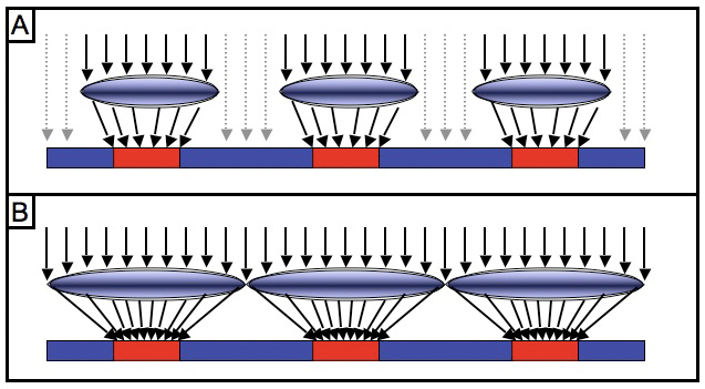
Fig. 2.5.2:
Gapless microlenses. Gapped microlenses (A) allow
some light to be lost, because it misses the photosite. Gapless
microlenses (B) capture nearly all of the incoming light and
channel it toward the photosensitive region of the substrate.
Another recent technological development that was
discussed in section 2.3.4 is the use of back-illuminated CMOS, in which the
attendant circuitry for each photodiode is moved out of the light path
and will therefore no longer interfere with the effective absorption of
incident photons. Exactly how popular this latter technology will
become, and the degree to which it is obviated by the more effective
use of microlenses, remains to be seen.
Yet another way to reduce sampling error (i.e., photon noise), in the case of
sensors with an overabundance of pixels, is to combine photon counts
from several nearby photosites so as to improve samples sizes for
photon measurements. This technique is called binning (or pooling of samples), and has been
known for some time, but has remained impractical until just recently,
for two reasons. First, binning drastically reduces the number of
pixels in the final image, typically by a factor of two or four, so
that it’s really not practical for general-purpose imaging with an
image sensor having fewer than about 12 MP (for two-way binning) or 24
MP (for four-way binning). Second, the use of a standard Bayer pattern (a particular
arrangement of red, green, and blue photosites on the sensor) made
binning difficult, because same-color photosites aren’t next to each
other on the sensor, so binning them tended to blur the image by
combining photon counts from pixels some distance apart. A recent
attempt (by camera maker Fujifilm)
to resolve the latter issue involved rearranging the colored photosites
so as to place same-color photosites next to each other (unlike in the
Bayer pattern), so that pairs of adjacent photosites could be
combined. As a result, users now have the choice of operating the
camera in a high-resolution (12 MP) mode for bright scenes, or at a
lower resolution (6 MP) when light is scarce, with the binning in the
low-res mode helping to reduce the photon noise in poorly-lit
conditions.
One issue which I’ve only rarely seen addressed, as
of yet, is the so-called full-well
capacity of the photodiodes, which is simply the number of
electrons that can be stored in the photosite. The issue is that
each photon typically releases one electron in the silicon matrix of
the photodiode, so that increasing the light transmission to your
sensor will increase the number of arriving photons but may not
increase the number of electrons actually counted at the appropriate
photosite if the upper limit (the full-well
capacity) has been reached. Additional photons will,
presumably, continue to liberate electrons from the (impure) silicon
matrix to flow through the induced electrical field of the photodiode,
but without sufficient numbers of electron
holes (places for those electrons to reside) many electrons may
continue along the direction of the field and eventually end up in the
well of another photodiode. In this way, photons striking one
photosite can end up being counted at another photosite, resulting in
yet another type of noise. Keep an eye out for reports of
advances involving improved well capacities, or that otherwise limit
electron travel between photosites, since these may fundamentally
improve baseline noise characteristics of image sensors and therefore
improve high-ISO performance. A related avenue for possible
future improvement relates to a sensor’s quantum efficiency, or sensitivity
to different wavelengths of light.
One method which deserves special mention here
(though we’ll re-iterate this message numerous times throughout this
book) for reducing noise, or more precisely, for improving signal-to-noise ratio (S/N), is a
technique applied by users of
digital cameras rather than by manufacturers. The method is
called exposing to the right
(abbreviated ETTR) and results in more bits of information being used
to represent your image. This method can reduce the incidence of
certain forms of “noise” originating in the digital
domain. The
idea is simply to adjust the settings on your camera so as to produce
images that are as bright as possible without clipping any
highlights. Because brighter pixels are (on average) represented
using more bits in the image
file, less information is lost during discretization
(analog-to-digital conversion, or ADC)
than if you had exposed for a darker image. During conversion of
the RAW image to JPEG, you can then reduce the image brightness back to
a more natural-looking level without sacrificing information, since
you’ll ideally be working in a 16-bit color space.
This technique and its benefits
are discussed in greater detail in Chapter 6. Here we’ll just
note a few things related to the use of ISO to perform ETTR.
First, if you can perform ETTR (exposing to the right) by adjusting
only the shutter speed and/or aperture, while keeping ISO very low,
you’ll be both maximizing the number of bits allocated to your image’s
detail and at the same time minimizing photon noise. Exposing to
the right via shutter speed and aperture (but not by using higher ISO’s) reduces
photon noise by allowing the sensor to collect more photons, thereby
reducing sampling error and ensuring a more accurate measurement of
color information from the incoming light. Remember, collecting
more light allows a more accurate measurement of the individual colors
making up that light. If instead you expose to the right by
increasing the ISO setting, you’ll be getting the benefit of better bit
utilization (since you’ll have brighter pixels, which are generally
allocated more bits in the RAW file than darker pixels), but you won’t
be reducing photon noise at all, since you’re not collecting more light
(you’re just amplifying the signal after it’s already been measured by
the sensor).
Just remember that ISO doesn’t affect the
sensitivity of the silicon atoms in your sensor to photons; it simply
multiplies the photon counts after
the photons have already been counted. When applying the ETTR
technique, if you have to do it by increasing the ISO, that’s OK:
you’ll still get some benefit due to better bit utilization. But
if you can do it via shutter speed and/or aperture instead of higher
ISO,
you’ll also be reaping the benefits of lower photon noise.
2.5.4 Other
Costs of High ISO
Besides increased noise, there may
be other costs to the use of higher ISO settings in a particular camera
model, and you should be careful to find out about these before
finalizing your assessment of any camera model you’re considering
purchasing. A common cost of high ISO is a reduction in buffer size (sometimes called burst rate). The buffer is
where images are stored between the time they’re captured and the time
they’re written to the memory card. Because images from today’s
cameras are typically very large (often well over 10 Megabytes), and
because writing to memory cards is typically very slow, the images
captured by your camera can take several seconds to be written to the
card. They need some place to be stored before being written to
the card, and that place is the buffer.
If you quickly take another photo while the first photo is still being
written to the card, it too has to be stored in the buffer. When
shooting action scenes (such as birds in flight), it’s common practice
to continuously hold down the shutter-release button so that the camera
takes a series of shots in very rapid succession (up to about 10 frames
per second for today’s pro camera bodies). Because today’s memory
cards can’t accept images at that speed, larger buffers are needed in
today’s cameras for storing the images taken during intense bursts of
action, till they can be written to the memory card. For
technical reasons, the use of higher ISO settings sometimes forces the
camera to reduce the available buffer size for action shooting.
For example, the camera that I currently use, the Canon EOS 1D Mark
III, reduces the available buffer size by 2 to 6 shots when shooting at
ISO 640 or greater. In intense action scenarios, I’ve
occasionally run up against the buffer limit, and had to stop shooting
(i.e. lost potentially great shots) until the buffer cleared, as
previously-captured images were in the process of being written to the
memory card. Though this delay can be reduced somewhat by using
faster (and more expensive) memory cards, it’s still worthwhile to
investigate whether the camera you’re thinking of buying inflicts a
buffer-size penalty for shooting at higher ISO’s, and how significant
that penalty is.
|
|
|